
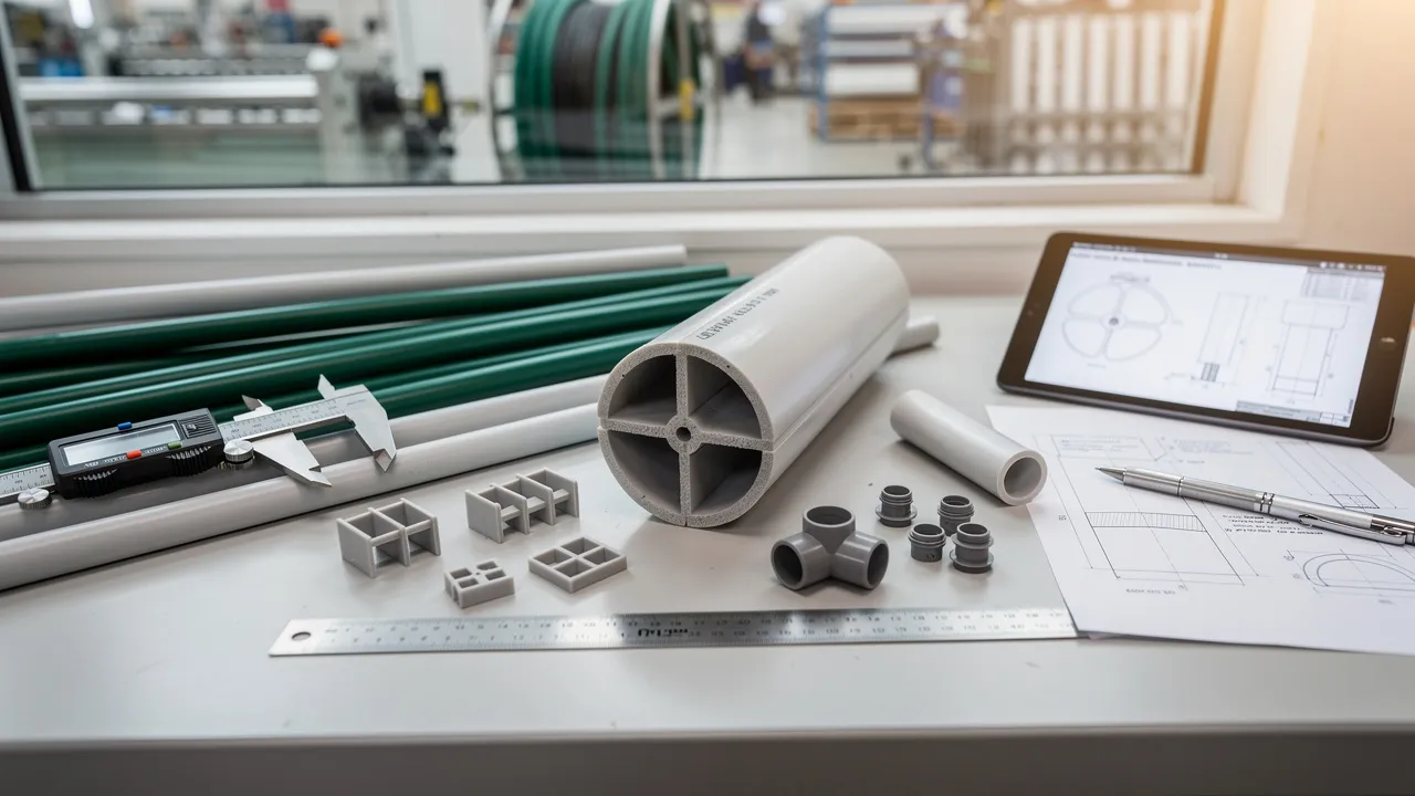
Start with the cross-section and the job it must perform
A plastic extrusion design guide starts with one process-fit question: does your part maintain a constant cross-section along its length? Extrusion is suited to parts with a constant cross-section, such as profiles, tubing, and rod. That makes it relevant to many pipe, tube, conduit, trim, and equipment-component requirements, but the cross-section alone does not establish whether a proposed design will meet its service demands.
Define the component’s job before you refine its shape. For an OEM irrigation part, that job might involve carrying fluid, supporting another component, guiding movement, protecting a drive element, retaining a mating part, or transferring a load. These functions lead to different design questions about openings, interfaces, wall thickness, flexibility, dimensional control, and exposure.
Write the functional description in one sentence, then separate what the part must do from how you expect it to be manufactured. For example, describe a tube by its connection points, flow or clearance requirement, cut length, handling conditions, and operating environment before selecting a wall dimension or resin. This keeps the specification open to a manufacturability review rather than turning an early assumption into a fixed requirement.
Use the following opening record:
- Part function: what the component must support, contain, guide, protect, or connect.
- Extrusion path: the constant cross-section you expect to run continuously.
- Interfaces: the parts it touches, receives, fits over, fits inside, or attaches to.
- Service conditions: moisture, outdoor exposure, temperature, chemicals, abrasion, impact, pressure, and handling demands that require review.
- Release question: which requirements are already defined, and which require supplier or engineering validation?
If the part changes substantially along its length, identify those changes separately. A constant extruded section may still be cut, drilled, assembled, or combined with other components after production, but each added operation belongs in the specification and RFQ.
Use a feature-level review record instead of a rule checklist
A feature-level review record gives you a better design discussion than a list of blanket extrusion rules. Extrusion design rules are not absolute: a feature’s functional benefit may justify additional tooling or process complexity. The practical question is not whether a feature appears on a generic “avoid” list. It is whether the feature earns its manufacturing cost and risk in your application.
Build one row for every feature that can affect function, process stability, inspection, assembly, or cost. Use this matrix before requesting tooling or a firm production quotation:
| Feature or requirement | What you need to define | Manufacturing concern to raise | Status | Supplier-validation question |
|---|---|---|---|---|
| Cross-section | Solid or hollow shape, openings, interfaces, and orientation | Die complexity, support, flow, and cooling | Defined, revise, or validate | Can this section run as drawn? |
| Wall region | Nominal wall, transitions, local thick or thin areas | Uneven cooling, shrinkage, warpage, or collapse | Defined, revise, or validate | Which wall regions need redesign or process control? |
| Functional detail | Rib, corner, groove, lip, flange, or retention feature | Flow restriction, sharp radius, asymmetry, or added tooling | Defined, retain, or revise | What is the effect of keeping this feature? |
| Critical dimension | Fit, clearance, sealing, flow, or interface dimension | Capability depends on geometry, material, tooling, cooling, and process | Defined or validate | How will this feature be controlled and inspected? |
| Service condition | Moisture, outdoor exposure, UV, temperature, chemicals, abrasion, pressure, impact, or handling | Resin and stabilization choices require application review | Defined or validate | What material and process questions remain open? |
| Production requirement | Annual demand, cut length, packaging, delivery, and change control | Tooling and process decisions depend on the production plan | Defined or validate | What assumptions affect the quotation and schedule? |
Use defined when your team has an agreed requirement and an appropriate way to communicate it. Use revise when the feature is understood but the proposed geometry creates a concern. Use validate when the requirement or capability depends on application conditions, material selection, tooling, or a supplier trial.
The matrix also creates traceability. If someone proposes changing a radius, wall transition, material, or tolerance, record which functional requirement the change protects and which manufacturing question it resolves. Keep features that matter to performance visible, even when they add process complexity. Ask for a manufacturability response rather than deleting them automatically.

Record the geometry that defines the extrusion path
The geometry record should let a supplier understand the section without inferring missing information from a product name. Start with the cross-sectional drawing or a dimensioned sketch, then identify every feature that continues along the extrusion path.
Record these items:
- Section type: solid, hollow, open, closed, tubular, or profile-shaped.
- Overall dimensions: outside width, height, diameter, and any envelope limits.
- Internal geometry: bore size, internal openings, webs, voids, and access points.
- Interfaces: grooves, lips, ribs, flanges, shoulders, connection areas, and mating surfaces.
- Orientation: the side that faces outward, carries a load, receives a mating part, or requires a controlled appearance.
- Length and cut plan: continuous run length, finished cut lengths, end treatment, and acceptable cut variation.
- Corners and transitions: internal and external radii, wall transitions, steps, tapers, and asymmetric regions.
- Secondary operations: drilling, punching, cutting, assembly, marking, or other work after extrusion.
Extrusion is suited to parts with a constant cross-section, so distinguish continuous section geometry from features created after cutting or assembly. A hollow profile requires internal mandrel support in the die, while a solid profile is simpler to tool but can still have warpage risks. That distinction belongs in your tooling discussion, not just in the drawing title.
Mark unsupported or highly asymmetric areas on the drawing instead of assuming that a supplier will interpret them as ordinary geometry. Poorly formed corners can result from geometry, cooling, flow, support, or radius problems, so flag corner geometry for a process discussion. The point is not to predict a defect from a drawing alone. The point is to identify where the design review needs a process answer.
For each feature, add a short function statement. “Retains the insert,” “maintains clearance,” or “supports the hose connection” gives a supplier a reason to protect the feature during manufacturability review. A feature without a stated function is easier to simplify; a feature with a clear function can be weighed against the added tooling or process work.
Review wall thickness as a stability question
Wall thickness is not only a strength number. It also affects how the section fills, cools, shrinks, holds its shape, and supports any hollow area. Treat nominal wall thickness, variation, and transitions as a connected design review.
Design guidance identifies uniform walls as a key extrusion rule; variations above roughly 25% of nominal wall thickness can create differential shrinkage and warpage. Use that figure as a warning point from the guidance, not as a universal acceptance limit for your part. The material, section, process, and function still require project-specific review.
Document the following for every wall region:
- Nominal wall thickness and the measurement location.
- Thick or thin zones created by ribs, corners, bosses, lips, or transitions.
- The reason each local variation exists.
- The direction in which the section must remain straight, round, flat, or aligned.
- Whether an internal void must remain open and dimensionally stable.
- Which wall dimensions affect fit, flow, pressure, flexibility, weight, or assembly.
Avoid making the drawing appear precise while leaving the transition logic undefined. Show where a thick region begins, how it blends into the surrounding wall, and which dimensions control the functional result. A supplier can then discuss whether the geometry, die, cooling approach, and inspection plan support the requirement.
For hollow tubing or pipe, identify the internal and external dimensions separately. The internal dimension may control clearance or flow, while the external dimension may control a clamp, guide, sleeve, or machine interface. Do not assume that a nominal wall calculated from those two dimensions will be equally controlled around the full section. Ask how the proposed geometry will be supported and checked.
Your decision record should end with one of three entries: the wall is defined for supplier review, the wall transition needs revision, or the wall requirement remains open until tooling and process capability are discussed.

Separate functional features from manufacturability compromises
A manufacturable extrusion is not necessarily the one with the fewest features. A simplified section can lose the rib, corner, groove, or asymmetry that makes the part work in your equipment.
Review each feature through four questions:
- What function does it protect? State the load, interface, clearance, retention, sealing, flow, guidance, protection, or assembly purpose.
- What happens if it changes? Describe the consequence of removing it, reducing it, changing its radius, or moving it.
- What manufacturing concern does it create? Identify possible flow restriction, uneven cooling, unsupported voids, sharp corners, asymmetry, or inspection difficulty.
- What decision is needed? Mark the feature as retain, revise, or validate, and write the question a supplier must answer.
A rib that maintains spacing may deserve to remain while its transition is reviewed. A sharp internal corner that contributes no clear function may be a candidate for revision. A hollow area may be necessary for clearance or weight, but its support and dimensional control need a specific tooling discussion. Do not convert these examples into universal geometry rules; use them to structure the feature review.
Defect symptoms can help you frame that conversation. The same visible symptom can have more than one possible cause, so avoid assigning a correction before the supplier reviews the section and process.
End every branch with a clear action:
- Retain: keep the feature on the drawing and ask how the process will support it.
- Revise: change the geometry, then update the function and tolerance record.
- Validate: keep the requirement open until tooling, sampling, or process review provides a project-specific answer.
Describe the service environment without prescribing a resin
The service environment belongs in the specification before you settle on a resin or stabilization package. For irrigation equipment, record the actual exposure and operating demands rather than relying on a broad label such as “outdoor use.” The same approach applies to industrial OEM tubing, covers, guards, and profiles.
Create an environment record with these prompts:
- Moisture: water contact, immersion, drainage, condensation, and the expected duration of exposure.
- Outdoor and UV exposure: direct sunlight, shaded installation, seasonal exposure, and whether the part is stored outdoors before installation.
- Temperature: expected operating range, storage range, short-term extremes, and heat from adjacent equipment.
- Chemical contact: fertilizers, treatment chemicals, oils, cleaners, fuels, or other substances that may contact the part.
- Mechanical demand: pressure, vacuum, impact, abrasion, flexing, vibration, clamping, bending, and repeated movement.
- Installation and handling: pulling, cutting, fastening, stacking, transport, field handling, and contact with other components.
- Service duration: expected operating life, inspection interval, replacement cycle, and exposure changes over that period.
Do not write “UV resistant,” “chemical resistant,” or “suitable for pressure” without defining the condition behind the phrase. Add the exposure level or test requirement only when your engineering team has established it, and leave the material or additive choice open for application-specific review.
Resin selection affects processing because melt viscosity, shrink rate, and thermal expansion differ across resin families such as PVC, HDPE, ABS, and TPE. That processing difference is one reason a resin choice cannot be separated from geometry, wall thickness, tolerances, cooling, and the service environment. State a required resin when your project has already established one; otherwise identify the performance and processing questions that the supplier and your engineering team must resolve.
For a supplier inquiry, separate three fields: required, preferred, and open for recommendation or validation. This prevents a preferred material from being mistaken for a confirmed application requirement and gives the supplier room to identify a process issue without silently changing your design intent.
Make tolerances feature-specific and function-led
A useful tolerance specification explains what must fit, seal, clear, align, flow, or remain stable. Avoid placing one blanket tolerance on every dimension when different features serve different functions.
There is no single tolerance for every plastic extrusion; achievable tolerances depend on geometry, dimensions, material behavior, tooling, cooling, process conditions, and the controlled feature. That means a tolerance request should be linked to a feature and a measurement purpose, not copied from a previous part or selected without regard to the section.
Build a tolerance register with these fields:
- Feature: the exact dimension, surface, profile location, or relationship being controlled.
- Function: fit, clearance, sealing, flow, alignment, retention, appearance, or another defined purpose.
- Datum or reference: the surface, centerline, axis, or interface used for measurement.
- Permitted variation: the tolerance your engineering team has established for the function.
- Measurement condition: the part state, location, temperature, cut length, or setup that matters to the result.
- Disposition: critical for approval, monitored during production, or informational.
- Supplier question: how the feature will be produced, measured, and managed.
Call out critical dimensions separately from reference dimensions. If an outside diameter controls a clamp but a local surface mark does not affect assembly, they should not receive the same attention or acceptance logic. If straightness, roundness, twist, or bow affects installation, record the requirement as a relationship or form characteristic rather than hiding it in a dimensional note.
Ask for a capability discussion around each critical feature before freezing the drawing. Keep any application-specific tolerance, pressure, seal, or fit decision with the qualified engineering authority for the part.
Connect the drawing to die, calibration, and process questions
Your drawing describes the desired section; the tooling and process discussion explains how that section will be formed, cooled, supported, and checked. Connect each difficult feature to a question about the die, hollow-section support, calibration, cooling, line speed, handling, and inspection rather than treating tooling as a separate purchasing step.
Hollow profiles require internal mandrel support in the die, while solid profiles are simpler to tool but can still have warpage risks. Ask how the proposed tooling will maintain the internal void, preserve the critical walls, and control the orientation of an asymmetric section. If the drawing contains a sharp internal radius, abrupt wall change, or unsupported opening, identify it as a design-review item instead of assuming the die will correct it.
Published planning ranges vary with scope. One comparison lists 4–12 weeks for complex hollow-profile tooling. For a new U.S. extrusion die, the cited guide lists a typical 4–10-week lead time. These ranges overlap but do not describe the same project, so they should not be combined into a universal schedule or treated as a commitment for your part.
Ask the supplier to separate the following stages:
- drawing and manufacturability review;
- die design and approval;
- die fabrication;
- calibration or downstream tooling review;
- first trial or sample run;
- dimensional and functional evaluation;
- drawing, tooling, or process corrections; and
- production release.
Keep the schedule conditional until the supplier reviews the actual drawing, material status, tolerance register, tooling scope, and validation plan.

Define what must be inspected and approved
Inspection begins with the function of the part, not with a generic list of measurements. Your record should identify which characteristics determine release, which are monitored during production, and which are recorded for information.
Define these approval inputs before requesting samples:
- Critical dimensions: the features that control fit, clearance, sealing, flow, alignment, retention, or installation.
- Profile form: bow, twist, straightness, roundness, flatness, or another relationship that affects use.
- Wall and hollow-section condition: internal and external dimensions, continuity, collapse limits, and local transitions that matter to function.
- Surface and appearance: visible lines, marks, scratches, discoloration, or other conditions that your application treats as unacceptable or acceptable.
- Cut and end condition: finished length, squareness, burrs, openings, and secondary operations.
- Sampling and approval point: what must be reviewed at first article, during a trial, or during ongoing production.
- Documentation: drawing revision, inspection record, material identification, approved sample, and change-notification expectations.
The approval categories above provide the basis for deciding where measurement effort belongs. A dimension that controls a mating connection needs a different approval question from an exterior surface that has no functional interface.
Defect language should also be specific. Describe the condition you need controlled, then ask how it will be identified and dispositioned. Do not invent an acceptance limit simply because a drawing needs a number; assign open items for engineering and supplier resolution.
Before approval, attach the inspection record to the same revision of the drawing and feature matrix used for the RFQ. That connection prevents a sample from being approved against a different interpretation of the requirement.
Add production and commercial inputs to the technical record
A technically clear drawing can still produce an incomplete quotation if the production brief is missing. Add commercial and operating assumptions to the same record so the supplier can evaluate tooling, run quantities, cut lengths, packaging, and delivery as one project.
Include these inputs:
- annual footage, annual unit demand, and expected order pattern;
- forecast horizon and any ramp-up or seasonal demand;
- continuous extrusion length, finished cut lengths, and allowable cut variation;
- packaging, nesting, protection, labeling, and pallet or container requirements;
- delivery destinations, requested shipment cadence, and storage constraints;
- prototype, pilot, first production, and recurring production needs;
- tooling ownership, maintenance, storage, and transfer assumptions;
- drawing revision, material status, sample status, and change-control expectations; and
- commercial items that must be separated, such as tooling, sample work, production parts, packaging, freight, and secondary operations.
Do not ask for a unit price without identifying the basis of the unit. A price per foot, piece, coil, cut length, or shipment can represent different production assumptions. State the expected cut length and packaging method, then ask how setup, changeover, scrap, inspection, and minimum run assumptions affect the quotation.
For planning context, one comparison lists custom profile tooling at $1,000–$15,000 and a complex injection-molding part mold at $10,000–$100,000 or more. Those figures describe a comparison, not a quotation for your extrusion. Use them only to recognize that tooling should be listed as its own commercial decision and reviewed against the actual section and process.
The same comparison lists 4–12 weeks for complex hollow-profile tooling. Treat that range as planning context rather than a promised delivery date. Ask for a project schedule that identifies drawing approval, tooling, trial, correction, sample approval, and production release separately.
Mark every commercial field as confirmed, estimated, or open. An open field should produce a direct question in the RFQ rather than an unspoken assumption in the supplier’s response.
Use a feature-level extrusion design review before tooling
A feature-level design review keeps the part’s purpose connected to the decisions that affect extrusion feasibility. Instead of applying a rule checklist to the entire profile, create one review row for each feature that matters to fit, function, service, or production.
Use these fields for every row:
- Feature and function: identify the feature and the job it must perform.
- Proposed design: record the cross-sectional shape, dimensions, wall region, interface, radius, transition, opening, or other relevant detail.
- Service condition: note the exposure, temperature, chemicals, pressure, abrasion, impact, flexing, vibration, moisture, or handling demand that affects the feature.
- Manufacturing concern: state the question involving flow, cooling, support, tooling, calibration, warpage, surface quality, or dimensional control.
- Tolerance and inspection point: identify the datum or reference, allowable variation, measurement condition, and appearance or defect limit that matter to the function.
- Decision status: mark the feature retain, revise, or validate.
- Open question: write the specific question that must be answered before the design or tooling decision is closed.
The status is a decision aid, not a declaration that a design is suitable. Use retain when the feature’s purpose and manufacturing rationale are documented. Use revise when the feature creates a known geometry, cooling, flow, support, radius, or tolerance concern and its function can be met another way. Use validate when the feature is functionally important but the result depends on material behavior, tooling, cooling, process conditions, or a project-specific trial.
Build the review around features
Begin with the constant cross-section that makes extrusion relevant. Record whether the part is a profile, tube, pipe, or another continuous section, then describe how it interfaces with the surrounding equipment. For a hollow section, identify the openings, internal features, and support questions that affect the die and calibration. For a solid section, record the geometry that could affect cooling, shrinkage, or warpage. The purpose is to expose the manufacturing question attached to each feature rather than to label one construction as universally preferable.
Treat wall thickness as a feature group rather than a single number. Record nominal wall regions, transitions between heavy and light areas, and any location where an internal void or adjacent feature changes the section. A row marked validate should state whether the concern requires a geometry revision, tooling discussion, cooling review, or trial.
Separate functional geometry from geometry that is merely convenient. A corner, rib, transition, asymmetry, or unsupported feature may serve a real interface or load requirement. Record that reason before deciding whether to change it. The review question is therefore, “What does this feature accomplish, and what manufacturing consequence must be accepted or resolved?”
For each dimensional requirement, connect the number to its function. Identify fits, interfaces, sealing or flow-related dimensions, cut lengths, inspection datums, and any dimension that controls assembly or use. Use a feature-specific tolerance entry that records the permitted variation and how it will be assessed, rather than copying one blanket tolerance across the section. A row should therefore record the permitted variation and how it will be assessed, rather than copying one blanket tolerance across the section.
Keep material and service decisions together
Record the service environment beside the feature it affects. For irrigation pipe and tubing, the review may need fields for moisture, outdoor and UV exposure, temperature, chemicals, pressure, abrasion, impact, flexing, vibration, handling, and the relevant interfaces. The record should show which conditions are known, which require confirmation, and which could change the geometry or validation plan.
Do not turn the review into an unsupported resin recommendation. Mark the material as customer-specified, open for application review, or requiring input from the resin supplier or extrusion supplier. Keep the final material and stabilization decision tied to the actual service requirements and the responsible technical review.
Apply the matrix to OEM components
For a center-pivot pipe or drop tube, a review row can connect the section geometry to its interfaces, cut length, pressure or flow-related requirements, exposure, handling demands, and allowable dimensional variation. The decision may be validate where those requirements depend on the specific equipment or operating conditions. The row should ask what the supplier needs to review the section, rather than declaring that the design fits a particular machine or field condition.
For a hose weight or drive-shaft tube, record the feature’s actual interfaces and service demands, then identify the dimensional, impact, flexing, vibration, or handling questions that affect the design. The same matrix can be used for an industrial OEM profile: describe the fit or equipment function, identify the section features that support it, and connect each manufacturing concern to a status and an open question.
A completed set of rows should make contradictions visible. For example, a feature may be important to the equipment interface while also creating uneven cooling or a difficult tolerance. Marking it validate preserves the functional requirement without pretending that a general extrusion rule settles the trade-off. Marking it revise records that the function will be pursued through a different geometry. Marking it retain records why the existing feature remains part of the design.
Use the completed record for the supplier discussion
Before sending a drawing or preparing an RFQ, check that every feature affecting function has a stated purpose, service context, manufacturing concern, tolerance or inspection point, status, and open question. Attach the cross-section and its revision level, but let the feature rows carry the reasoning behind the drawing. Ask the supplier to respond to the marked questions about die scope, hollow-section support, cooling, process conditions, achievable tolerances, and any feature that remains in validate status.
The resulting record is useful because it preserves the design rationale while separating what is defined from what still needs supplier review. It also keeps application-specific assumptions visible: a proposed geometry, resin, tolerance, or performance expectation remains open until the relevant feature has been reviewed against the actual equipment and service conditions.
Use irrigation components as prompts, not proof of fit
Irrigation components make the review concrete, but an industry label does not prove that a proposed section fits a particular center-pivot machine or field condition. Use each component name as a prompt for the requirements record.
For a center-pivot pipe or tube, document the connection interfaces, internal and external dimensions, cut lengths, support points, pressure or flow requirements, outdoor and UV exposure, chemical contact, temperature, handling, and installation method. Identify whether the section is expected to remain rigid, flex during installation, support another part, or accommodate movement. Leave any material, wall, tolerance, or stabilization conclusion open until the application requirements are reviewed.
For a drop tube, ask what it must connect to, how it is supported, what movement it experiences, and which dimensions control installation and operation. For a hose weight, record the mating hose, retention method, load, impact, abrasion, and handling conditions. For a drive-shaft tube or cover, identify the rotating or moving interface, clearance, alignment, protection requirement, and exposure to debris or moisture. These prompts describe what to define; they do not establish suitability for a machine.
Use a component-specific worksheet:
- Component identity: pipe, tube, drop tube, hose weight, drive-shaft tube, cover, or another profile.
- Machine interface: connection, clamp, guide, sleeve, fastener, bearing area, or moving part.
- Functional load: containment, support, retention, protection, guidance, clearance, or movement.
- Environment: moisture, sunlight, temperature, chemicals, abrasion, impact, and handling.
- Critical features: dimensions, wall regions, openings, radii, interfaces, straightness, twist, or cut length.
- Validation question: what must be demonstrated before your team releases the part?
We provide tailored OEM solutions, including pipes, tubes, and flexible profiles. Our plastic extrusion profiles for pipe and tube shapes serve industries such as irrigation, construction, and automotive. For an irrigation inquiry, use those offerings as the starting point for a specific requirement discussion, not as a declaration that every proposed geometry or service condition is already approved.
Resolve contradictions and unknowns with supplier review
A complete RFQ does not eliminate uncertainty; it makes uncertainty visible and assignable. Use the feature matrix to identify what your team has defined, what needs design revision, and what the supplier or engineering authority must validate.
Tooling timing is one example. The different ranges reflect different scope and framing. Do not select one range as the schedule for your project; ask the supplier to identify the tooling scope, assumptions, trial plan, correction allowance, and production-release date.
Tolerance capability also requires a project-specific answer. When a supplier cannot confirm a tolerance from the drawing alone, mark the item as validate and request the next technical step, such as a design review, sample plan, or capability discussion.
Use this resolution sequence for every open item:
- Name the unknown: identify the exact feature, condition, or commercial assumption.
- Explain its consequence: state which function, schedule, cost, inspection decision, or release decision it affects.
- Ask for the required response: request a revision, capability statement, tooling comment, sample, measurement plan, or application review.
- Assign the decision: identify whether your engineering team, the supplier, the material provider, or another qualified authority must close it.
- Record the outcome: update the drawing, matrix, RFQ response, and approval status together.
Keep published ranges and general capability statements in the planning section of your record. Use confirmed project responses for the actual tooling decision, tolerance release, and production schedule.
Finish with a pre-RFQ decision gate
Before you release an RFQ, mark every feature and requirement as defined, revise, or validate. Attach the drawing, feature matrix, wall review, service record, tolerance register, tooling questions, inspection plan, production brief, and open-decision list as one controlled packet.
A defined item has an agreed requirement and a stated way to communicate or inspect it. A revise item needs a geometry, material, tolerance, or process change before you ask for final tooling assumptions. A validate item can move into supplier or engineering review, but it should not be treated as an approved performance outcome.
We offer expert advice on the design of plastic extrusion tubing and custom pipes. We provide expert custom profile extrusion services tailored for OEMs. Take your completed record into that discussion and ask for a response to each open feature, tooling assumption, tolerance priority, inspection question, and production requirement.
A qualified engineer must decide whether the proposed design is suitable for your specific machine, service conditions, regulatory requirements, and release criteria. Use the supplier conversation to improve the manufacturability record, then make the application-specific approval through the appropriate engineering process.
What should an OEM confirm before requesting a plastic extrusion quote?
What information should an OEM include in a plastic extrusion RFQ?
Include the part function, dimensioned cross-section, wall regions, interfaces, cut lengths, service environment, material status, feature-specific tolerances, inspection expectations, annual volume, packaging, delivery needs, secondary operations, tooling assumptions, and drawing revision. Clearly mark each item as defined, revise, or validate so the supplier can identify open decisions.
How do you know whether a part is suitable for plastic extrusion?
Extrusion is generally suited to parts with a constant cross-section, such as pipe, tube, rod, and continuous profiles. If the geometry changes substantially along its length, separate those features for cutting, drilling, assembly, or another process review rather than assuming continuous extrusion can produce the complete part.
What should be specified for center-pivot irrigation pipe or tubing?
Define the machine interfaces, internal and external dimensions, cut lengths, support points, flow or pressure requirements, outdoor and UV exposure, moisture, chemicals, temperature, abrasion, impact, handling, and installation method. These inputs frame the design review but do not establish a universally suitable resin, wall thickness, tolerance, or machine fit.
How long does it take to develop plastic extrusion tooling?
Published planning estimates vary by tooling scope. One comparison lists 4–12 weeks for complex hollow-profile tooling, while a U.S.-focused design guide lists 4–10 weeks for a new extrusion die. Treat these as planning context, not a project commitment; confirm the schedule after reviewing the drawing, tooling scope, trial plan, corrections, and approval steps.
How should material selection be handled when designing an extruded plastic part?
Start with the required performance and service conditions rather than choosing a resin from the part name alone. Record moisture, UV exposure, temperature, chemicals, pressure, abrasion, impact, and flexibility requirements, then identify the resin as required, preferred, or open for review. Resin families differ in viscosity, shrink rate, and thermal expansion, so the selection must be considered with geometry, processing, and application approval.
How should tolerances be specified for an extruded pipe, tube, or profile?
Tie each tolerance to a specific function such as fit, clearance, sealing, flow, alignment, retention, or installation. Identify the feature, datum, measurement condition, permitted variation, and approval status. There is no single tolerance for every extrusion; capability depends on the geometry, material, tooling, cooling, process conditions, and feature being controlled.


