
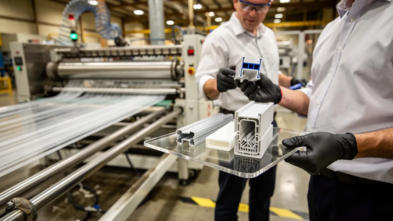
Read “core extrusion” as a cross-sectional description
In this context, “core” names a region inside the profile that must be described by its material, structure, and function. “Core extrusion” is therefore a term to unpack, not a complete process specification. Plastic extrusion melts thermoplastic material and forces it through a shaped die to create long, continuous forms with a consistent cross-section. The buyer’s first task is to identify what the word “core” refers to in the proposed cross-section.
When the required structure has distinct material zones, co-extrusion is one possible route: two or more plastic melt streams pass through a common die or extrusion head to form one continuous profile. Co-extrusion normally creates a layered structure in which each layer contributes a key property to product performance. A rigid body with a flexible sealing lip is one supported example of distinct zones. The finished geometry may be an open channel, a closed section, or another custom profile.
A profile description also needs dimensions and length expectations because cooling and cutting affect the finished part. Plastic conducts heat away 2,000 times more slowly than steel, so plastics are difficult to cool quickly. A 48.00-inch nominal extrusion with a plus-or-minus 0.5-inch length tolerance may measure from 47.50 to 48.50 inches and remain within that stated length specification. Define the nominal length, allowable variation, and function before discussing tooling.
Read “core” from the cross-section, not from the process name. Mark the central region, the surrounding region, each interface, and any open or hollow area. Then state the job assigned to each region in plain language. This mapping lets the supplier discuss whether the drawing points toward a single-material profile or a co-extruded profile.
Separate single-material extrusion from co-extrusion
Single-material extrusion uses one resin that is melted and pushed through a die to form a continuous profile. This approach fits a part whose required functions can be met by one material throughout the cross-section. If your drawing shows one material, one continuous wall structure, and no separate functional zone, describe the request as a single-material profile rather than adding a layered process term.
Co-extrusion combines two or more plastic melt streams through a common die to form one continuous profile. Co-extrusion requires a separate extruder for each distinct material. The process can place materials in different cross-sectional zones, so your brief should identify the core, skin, lip, layer, or other area that performs each defined function.
Feed-block co-extrusion merges melt streams upstream of the die, while die co-extrusion merges separate melt paths close to the die exit. Die co-extrusion can independently control individual layer thickness and flow rate and can handle polymers with substantially differing viscosities and melt temperatures. You do not need to choose between these arrangements before the discussion; identify the material zones, dimensions, and required function so the extrusion professional can assess the suitable route.
Your project brief should answer one classification question first: does the part need one resin throughout, or does it need distinct material zones in one continuous profile? A single-material request belongs in the first category. A core, skin, flexible lip, or other separate zone belongs in the second category and calls for a co-extrusion discussion.

Use the term to separate architecture from process
The word “core” answers a location question; it does not answer the product-function question. A proposed zone may be tied to structural support, flexibility, or a decorative surface when the project requires it. Co-extrusion can place distinct material zones in one profile for those roles. When the proposed zones have no separate jobs, retain a single-material profile as the comparison route.
Co-extrusion can remove an assembly operation, improve durability, and cost less per finished part than the single-material alternative it replaces when it is used for the right reasons. The described co-extrusion process bonds layers while molten to create a unified component without adhesives or secondary assembly. Compare that architecture with your present part structure: identify the operation it could replace and the property each material would contribute.
Low-volume parts with no assembly step to eliminate are usually better served by a single-material profile, possibly in a different resin. Use that comparison as a screening question rather than a final process decision. Ask whether the second material removes work, adds a required function, or changes the product structure enough to justify further review. If no distinct job exists for the additional zone, bring a single-material alternative into the supplier conversation.
The architecture should earn its place through a clear product trade-off. Record the function assigned to the core, the function assigned to the outer zone, and the assembly or separate component that the combined profile could replace. If those entries are blank, describe the part as a single-material candidate and ask for that route to be considered alongside co-extrusion.
Define the interface before choosing the architecture
Material interface adhesion is a design question whenever two polymer zones must remain together in service. Dissimilar polymers with low interlayer adhesion can cause multilayer co-extruded tubing to be subject to delamination. When selecting polymers for a multilayer structure, consider whether adjacent layers can form and retain the required bond. Put the interface between the core and skin on the project question list instead of treating the material names as sufficient.
A tie layer can be used between hard-to-bond polymer layers to help hold the layers together and resist delamination. A co-extruded adhesive bonding layer, commonly called a Tie layer, can hold polymer layers together and help them resist delamination. Ask whether the proposed structure needs such an intermediate layer, what material pair it addresses, and how the interface will be assessed. Leave the answer to qualified extrusion review.
Material choice must match the conditions assigned to each zone. PVC, polyethylene, and polypropylene have different properties that affect their extrusion performance. Rigid plastics are useful when durability and impact resistance matter, while flexible plastics can be engineered to mimic rubber-like physical properties. Record operating temperature, UV exposure, coloration or opacity, flame-resistance needs, chemical exposure, and intended function so the material discussion has defined conditions.
Your interface review should answer four practical questions: which materials meet the requirements of each zone, whether the materials can bond, whether an intermediate bonding layer is needed, and which service conditions could challenge the interface. Put the answers beside the cross-section rather than leaving them in a general material note. That record gives the extrusion professional a specific basis for reviewing the architecture.

Resolve the drawing details behind the term
Use the drawing to turn the label into measurable geometry. Show the core boundary, surrounding region, interfaces, wall thicknesses, openings, radii, and features tied to fit or function. Extrusion tolerances depend on geometry, dimensions, material behavior, tooling, cooling, process conditions, and how the finished profile is measured. The drawing should distinguish dimensions that control the part’s function from descriptive geometry.
Record wall thickness wherever the core and surrounding region meet. Uniform wall thickness helps prevent warping and internal stresses during cooling. Separately, wall-thickness variation can make flow difficult to regulate and distort the finished profile. Internal detail in hollow thermoplastic sections can be difficult to achieve because the inside cannot be accessed to hold the detail during calibration.
Length tolerance is affected by material, operating environment, function, and profile geometry. The measurement method is a separate part of dimensional review. Review critical dimensional requirements with the extrusion supplier before tooling.
Your drawing review should leave no critical feature unnamed. Check these items before sending it to an extruder:
- Overall profile dimensions and the boundary of each material zone.
- Wall thicknesses, hollow areas, openings, radii, and deliberate transitions.
- Fit- or function-critical dimensions with their allowable variation.
- The measurement method and the condition in which the part is evaluated.
This list turns “core” and “skin” into dimensions that can be discussed before tooling.
State the unresolved meaning in an RFQ
An RFQ should translate the term before it asks for a manufacturing route. State whether the core is a distinct material zone or a cellular or foam region, show its boundary on the cross-section, and name the function assigned to it. Include the surrounding material, intended use and exposure, critical dimensions, tolerances, and measurement method. The supplier can then address whether single-material extrusion or co-extrusion fits the described structure.
Your RFQ questions should connect the drawing to the production route. Ask which features need design review, how the material interface will be evaluated, which dimensions can be held, how the profile will be cooled and calibrated, and how length will be cut and measured. Review critical dimensional requirements and agree on tolerances with the extrusion supplier before tooling. Ask for the assumptions behind any proposed tolerance or inspection method.
Supplier selection should examine engineering capability alongside price and capacity because profile design, material choice, and tooling development shape manufacturing stability. Request a clear response to the drawing, material structure, tolerance plan, tooling questions, inspection requirements, and production assumptions. Keep commercial terms separate from technical acceptance criteria. A comparable response makes it easier for you to identify which open questions must be resolved before release.
Escalate unresolved feasibility and risk questions before release
Material-interface questions should be resolved before tooling or production commitment when delamination could affect the part. Co-extrusion conditions can be optimized to avoid interlayer flow instabilities by controlling each extrudate's melt temperature and the velocity ratios of the melt streams. Escalate unresolved interface questions rather than releasing an unconfirmed architecture.
Safety, compliance, and production-continuity concerns require a defined decision path before design release. Stop at the open requirement, document the affected material, interface, dimension, or operating condition, and obtain qualified extrusion review before tooling or committing to production. If the decision affects a regulated or safety-related product, contact the responsible qualified professional or authority promptly and do not treat a general process description as approval for the specific part.
Before release, make sure the proposed architecture has an identified material pair, an interface review, defined critical dimensions, and an agreed measurement approach. Hold the project at that gate if a material, tolerance, or service condition remains unresolved. Seek qualified review before tooling when the unresolved point could affect safety, compliance, product continuity, or the bond between profile zones.
Bring the clarified requirement to Lincoln Plastics
We provide expert custom profile extrusion services tailored for OEMs. Bring a defined cross-section, assigned material structure, intended function, operating conditions, critical dimensions, tolerances, and open feasibility questions to the project discussion. A clear architecture gives the extrusion team a concrete basis for reviewing the requested profile and production route.
Prepare the drawing and requirement list before you begin the supplier conversation. Include the job of every zone, the dimensions that control fit, the conditions that affect service, and the questions that need engineering review. Keep the process name subordinate to the cross-section; the defined part is what allows the next discussion to address feasibility, tooling, tolerances, and production requirements.
What should you confirm before requesting an RFQ?
What does “core extrusion” mean in plastic manufacturing?
It describes a profile with a defined inner core and an outer skin or other distinct zone. The phrase is best treated as a description of cross-sectional architecture, not as confirmation of a specific production method. Ask the extruder whether the requirement calls for single-material extrusion, co-extrusion, or another route.
Is core extrusion the same as co-extrusion?
Not necessarily. Co-extrusion combines two or more plastic melt streams through a common die to form one continuous profile, while “core” identifies the arrangement or function of zones within that profile. A core-and-skin design may therefore require co-extrusion, but the supplier must confirm the feasible route and material interface.
What should an OEM confirm before approving a core-and-skin profile?
Confirm the material assigned to each zone, whether the materials can bond, whether a tie layer may be needed, the operating environment, critical dimensions, tolerances, measurement method, and intended function. Hold tooling or production release until unresolved interface, safety, compliance, or continuity concerns receive qualified review.
How should a buyer describe this requirement in an RFQ?
Provide a cross-section drawing that marks the core, skin, interfaces, wall thicknesses, hollow areas, and critical features. Add the selected material or material family for each zone, part length, service conditions, intended function, critical tolerances, inspection method, and open feasibility questions. Request the proposed production route and the assumptions behind its tolerance and inspection plan.
What can cause problems between the layers of a co-extruded profile?
Dissimilar polymers with low interlayer adhesion can be subject to delamination. Melt-flow conditions can also create instability at the interface. A tie layer may help hold hard-to-bond materials together, but material compatibility, interface design, and process conditions require supplier review for the specific profile.


